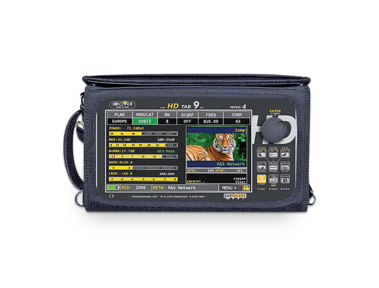
ROVER HD-TAB-9A
HD-TAB-9A by ROVER® Instruments can carry out analysis and measurements needed by broadcasters

- Home
- Product Info
- Other Manufacturers’ Products
- HD-TAB-9A ROVER
- General
- Option
- Specifications
- Download
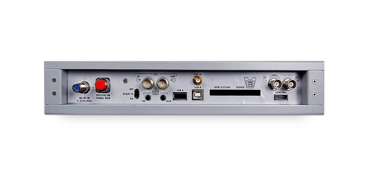
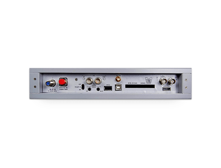
The HD TAB 9 has an “F” coaxial input to provide RF measurements. There are also ASI IN and OUT BNC connectors for looking at a transport stream (optional). An optical/electrical converter to carry out power and attenuation measurements is optional. There is a Common Interface slot for a CAM module and an HDMI® output (useful for connection to a monitor, or video projector, to reproduce what is being shown on the display). Two 3.5mm AV IN and AV OUT jacks provide a stereo audio input/output or an analog composite video picture, like the HDMI® OUT. There are two USB sockets for firmware upgrades, memory plan management and the recording of screenshots. On the right side, there are two RJ-45 sockets for a TS input over IP (optional) and LAN Ethernet for TS recording, data downloading and remote operation. The IPTV option provides an input for an ASI transport stream over IP, and will de-encapsulate the contents of the IP stream, carry out quality measurements and decode and display the services transported.
Features
- ASI Transport Stream Reader, Recorder, and Analyzer – based on ETR101 and 290 (HW & SW option)
- Decoded Picture Display
Dolby® AC-3 Audio (SW option) - MPEG-2 and MPEG-4
- RF TV/SAT/CATV Signal Level Meter Measurements: MER, PER, LDPC, BCH, aBER, bBER, EVM, Noise Margin, Average Power, Echoes/Microechoes/Pre-echoes in Real Time. CATV: Ingress, Leakage, Barscan & Tilt. Real-time Spectrum with MAX HOLD
- ATSC (HD TAB 9A for US, Canada and Mexico) or ISBD-T (HD TAB 9I for South America)
- 9-inch Color TFT High Brightness 16:10 Display
- Touch Screen
- LI-ion Polymer Battery for up to 6 hours of operation
- AC Adapter
- Carrying Case
- IPTV Analyzer – ASI over IP – RJ45 connector (HW & SW option)
- Optical – Power Meter – FC–ST–SC Interchangeable connector (HW & SW option)
- GPS – Position – GPS antenna Input with SMB connector (HW & SW option)
- HD ASI IN/OUT
Hardware and Software for ASI Input/Output, ETR 101-290 Transport Stream Analyzer, and Dolby AC3 Audio - HD Optical Input
Hardware and Software for Optical Input for PWR & SPECT with interchangeable connectors, ST/SC/FC - HD LAN IPTV/ASI
Hardware and Software for IPTV Quality Analyzer - IP to ASI/de-encapsulator
- HD GPS Receiver
GPS Receiver for Position & GPS Antenna Quality Test - DVB-T2 LITE
- DVB-C2
- DAB+ Measures
- LTE Autotest with Rejection Filter
- Network Delay Measurements for the DVB/T SFN network
- Signal coverage quality with GPS & “Prodrive Test” software
- SATEXPERT function dish pointing
- Mini Spectrum on Digital TV Picture
- Multi-purpose Bag
This carrying bag is made of a durable weather-resistant material. It allows the operator to work safely and without restrictions with both hands free by attaching the shoulder strap on to the bag or using the stand flap for operation on a counter surface. A sunlight-shield flap facilitates the visibility of the high brightness display.
| SUPPORTED STANDARDS | |
|---|---|
| Satellite: | DVB-S DVB-S2 Single Stream DVB-S2 Multi Stream (for Broadcast Multiple Network – transmitters feeding) |
| Television: | Analog TV: PAL, SECAM, NTSC-B/G/I/L/M/N DVB-T DVB-T2 Multi-PLP ATSC USA (option) GB20600 China (option) ISDB-T/Tb Japan & South America (option) |
| CATV: | DVB-C & Annex A DVB-C & Annex B (option) DVB-C2 EU (option) |
| Radio: | FM DAB (PWR MEAS.) |
| Optic (option): | Wavelengths: 1310 – 1490 (1625 for US) – 1550 |
| ASI: | ASI IN/OUT |
| LAN IPTV (option): | Encapsulated / De-encapsulated, IP to ASI, ASI to IP |
| RF Input Performances (5 – 2.250 MHz) | |
| 2 Selectable RF Inputs: | (1) 75 Ω “F” connector and (1) 50 Ω “N” connector, or on request (1) 50 Ω “N” connector and Optic Input, or (1) 75 Ω “F” connector and Optic Input with interchangeable connector ST/SC/FC, input selectable in the meter’s configuration menu |
| 50 Ω input matching (RL): | SAT >TV/CATV > 20dB ASI to IP |
| 75 Ω input matching (RL): | SAT >SAT > 16dB TV/CATV > 18dB |
| Audio Decoding | |
| MPEG-1 Layer I / II (ISO-IEC 13181-3) | |
| Dolby® Digital Plus | |
| Dolby® AC-3 | |
| AAC and HE AAC | |
| Video Decoding | |
| MPEG-2 MP@ML HDTV (ISO-IEC 13818-2) | |
| MPEG-4/AVC (ISO-IEC 14496-10) | |
| ITU-T H.264 | |
| ITU-T HEVC (2014 with interchangeable MPEG decoder board) | |
| DIGITAL SATELLITE | |
|---|---|
| Standard: | DVB-S (EN 300421) DVB-S2 Single Stream (DTH) DVB-S2 Multi Stream (for Broadcast Multiple Network – transmitters feeding) |
| RF Input: | 2 selectable inputs: (1) 75 Ω “F” connector and (1) 50 Ω “N” connector, or on request (1) 50 Ω “N” connector and Optic Input, or (1) 75 Ω “F” connector and Optic Input with interchangeable connector ST/SC/FC, input selectable in the meter’s configuration menu |
| Input Level Range: | 30 to 130dBµV – Max input power without damage +30 dBm (30V without simultaneous generation of internal voltage to the RF input) |
| Frequency Range: | 930 MHz to 2250 MHz |
| Frequency Resolution: | 1 MHz (with 100 KHz AFC Control) |
| Modulation: | QPSK, 8PSK, 16APSK, 32APSK |
| Roll Off: | Automatic selection in line with the selected standard |
| FEC: | 1/2, 1/3, 3/4, 5/6, 7/8 (DVB-S) 1/2, 2/3, 3/4, 5/6, 8/9, 9/10, 2/5, 3/5(DVB-S2) Automatic Selection |
| Symbol Rate: | DVB-S: 1 to 45MS/s – Full Automatic Selection DVB-S2: 2 to 45MS/s – Full Automatic Selection |
| ISI Selection (DVB-S2 Multistream): | From 1 to 10 |
| ISSY Synchronization (DVB-S2 Multistream): | Automatic Detection and Reading |
| Pilot (DVB-S2): | On, Off, Automatic Detection and Reading |
| FEC Frame (DVB-S2) | Normal, Short, Automatic Detection and Reading |
| LNB Control: | V (13V) / H (18V) Polarization 22kHz tone DiSEqC 1.0 and 2.0, SCR and MOTOR |
| Digital SAT Measurement Performances | |
| Synchronization Indication: | Unlock, Power Too Low, Lock |
| RF Power Level Accuracy: | 1dB typical (2dB Max) |
| RF Level Unit: | dBµV, dBmV, dBm – selectable |
| AFC – Capture Range: | 0 to 5MHz (step 100kHz) |
| LNB Frequency Error Measurement: | 0 to 5MHz (step 100kHz) |
| MER Range: | Up to 25dB |
| MER Accuracy: | 0.5dB up to 18dB – 1dB from 19 to 25dB |
| BER before Viterbi (DVB-S): | 1E-06 to 2E-02 |
| BER after Viterbi (DVB-S): | 1E-08 to 0 |
| BCH (DVB-S2): | 1E-06 to 1E-02 |
| LDPC (DVB-T2): | 1E-08 to 0 |
| PER (DVB-S2): | 1E-07 to 0 |
| Constellation: | SConstellation diagram with standard-specific grid and zoom |
| SAT Special Functions | |
| SAT SCR: | This function allows to control and verify the SCR LNB installation by checking the correct signal reception at each one of the LNB’s RF outputs via the spectrum analyzer or the SAT measurement interface. |
| Dual Feed LNB: | This function enables the user to verify the installation of a Dual Feed LNB dish, that can be either 9o and 13o or 19o and 23o or others; if the installation type is set to VARIABLE the user can perform the test on a couple of independent plans, at choice among those available in the meter. |
| DiSEqC Motor: | This function allows to control motorized dishes by moving the motor via DiSEqC commands. The control can be done using either the spectrum analyzer or the SAT measurement interface. |
| SAT Finder: | This function allows the user to determine the correctness of the dish pointing by detecting three transponders among those composing the requested satellite. |
| Buzzer & Noise Margin Graph: | This function could be activated on Satellite and Terrestrial canalizations. Its main AIM is to provide the user with a real time GRAPHIC diagram of the Noise Margin vs time. The measurement is also associated with a buzzer, synthetizing a tone the intensity of which is proportional to the signal quality. |
| SAT Point: | The aim of this function is to automatically set all spectrum parameters to facilitate dish pointing operations; the MAX HOLD & LIVE function guarantees perfect pointing at the maximum signal strength direction. |
| SATEXPERT Function (option): | Advanced Universal SAT pointer, the faster and accurate SAT FINDER (with optional electronic compass). |
| DIGITAL TERRESTRIAL TV | |
|---|---|
| Standard: | DVB-T/DVB-H (ETSI EN 300 744) DVB-T2 (ETSI EN 302 755) |
| RF Input: | 2 selectable inputs: (1) 75 Ω “F” connector and (1) 50 Ω “N” connector, or on request (1) 50 Ω “N” connector and Optic Input, or (1) 75 Ω “F” connector and Optic Input with interchangeable connector ST/SC/FC, input selectable in the meter’s configuration menu. |
| Input Level Range: | 29 to 130dBµV – Max input power without damage +30dBm (30V without simultaneous generation of internal voltage to the RF input) |
| Frequency Range: | 47MHz to 1000MHz |
| Frequency Resolution: | 50kHz |
| OFDM Modulation: | QPSK, 16QAM, 64QAM (DVB-T) 256QAM (DVB-T2) |
| FFT Mode: | 2k, 8k (DVB-T) 1k, 2k, 4k, 8k, 16k, 32k (DVB-T2) Automatic Selection |
| Guard Interval: | 1/4, 1/8, 1/16, 1/32 (DVB-T) 1/4, 1/8, 1/16, 1/32, 1/128, 19/128, 19/256 (DVB-T2) Automatic Selection |
| FEC: | 1/2, 2/3, 3/4, 5/6, 7/8 (DVB-T) 1/2, 2/3, 3/4, 5/6, 7/8, 3/5, 4/5 (DVB-T2) Automatic Selection |
| Channel Bandwidth: | 5MHz, 6MHz, 7MHz, 8MHz |
| Synchronization Indication: | Unlock, Power Too Low, Lock |
| RF Power Level Accuracy: | 0.5dB typical (1dB max) |
| RF Level Unit: | dBµV, dBmV, dBm – selectable |
| MER Range: | Up to 42dB |
| MER Accuracy: | 0.5dB up to 38dB, 0.7dB up to 40dB, 1.2dB up to 42dB |
| BER before Viterbi (DVB-T): | 1 E-06 to 1 E-02 |
| BER after Viterbi (DVB-T): | 1 E-08 to 0 |
| BCH (DVB-T2): | 1 E-06 to 1 E-01 |
| LDPC (DVB-T2): | 1 E-08 to 0 |
| PER (DVB-T2): | 1 E-07 to 0 |
| Constellation: | Constellation Diagram with standard-specific grid and zoom |
| Echoes Measurement: | -340 µs to 340 µs (4 selectable scales) |
| MER vs Carrier: | MER measurement for DVB-T and DVB-T2 signals with selectable carrier range: 1 to 32k carriers, normal or reverse. |
| Attenuation Test: | This function allows the verification at all ends of the distribution system so they receive the same signal strength, to make sure that there are no losses or other distribution issues. |
| DIGITAL CABLE CATV | |
|---|---|
| Standard | DVB-C (ETSI EN 300 429) DVB-C2 (ETSI EN 302 769) – optional |
| RF Input: | 2 selectable inputs: (1) 75 Ω “F” connector and (1) 50 Ω “N” connector, or on request (1) 50 Ω “N” connector and Optic Input, or (1) 75 Ω “F” connector and Optic Input with interchangeable connector ST/SC/FC, input selectable in the meter’s configuration menu. |
| Input Level Range: | 35 to 130dBµV – Max input power without damage +30dBm (30V without simultaneous generation of internal voltage to the RF input) |
| Frequency Range: | 4MHz to 1000MHz |
| Frequency Resolution: | 50kHz |
| Modulation: | 16QAM, 32QAM, 64QAM, 128QAM, 256QAM (DVB-C), 1024QAM (DVB-C2) |
| Symbol Rate: | 2 to 6.999MS/s – Automatic Selection |
| FEC: | |
| Channel Bandwidth: | 6MHz, 7MHz, 8MHz |
| CATV Measurement Performances | |
| Synchronization Indication: | Unlock, Power Too Low, Lock |
| RF Power Level Accuracy: | 0.5dB typical (1dB max) |
| RF Level Unit: | dBµV, dBmV, dBm – selectable |
| MER Range: | Up to 40dB |
| MER Accuracy: | 0.5dB typical |
| BER before Reed Solomon: | 1E-09 to 1E-02 |
| BER after Reed Solomon: | 1E-09 to 0 |
| Constellation: | Constellation diagram with standard-specific grid and zoom |
| Digital CATV Special Functions | |
| Leakage: | This function provides a technician with a tool to verify the presence of any signal leakage in a CATV distribution system. |
| Ingress: | This function lets the user verify the interference of the CATV return path, with a frequency band ranging from 4 to 66MHz |
| OPTICAL INPUT (Option) | |
|---|---|
| Input Interface: | FC/ST/SC – exchangeable connectors |
| Wavelength Range: | 1310 – 1490 (1625 for USA) – 1550 |
| Optical Input Level Range: | -40 dBm to +10 dBm |
| Optical Level Resolution: | 0.1dB |
| Optical Level Measurement Accuracy: | 0.5dB |
| ANALOG TV | |
|---|---|
| Standard: | PAL, SECAM, NTSC B/G/I/L/M/N |
| RF Input: | 2 selectable inputs: (1) 75 Ω “F” connector and (1) 50 Ω “N” connector, or on request (1) 50 Ω “N” connector and Optic Input, or (1) 75 Ω “F” connector and Optic Input with interchangeable connector ST/SC/FC, input selectable in the meter’s configuration menu. |
| Input Level Range: | 50 to 130 dBµV – Max input power without damage +30 dBm (30V without simultaneous generation of internal voltage to the RF input). |
| Frequency Range: | 47MHz to 1000MHz |
| Frequency Resolution: | 50kHz |
| Analog TV Measurement Performances | |
| Level Indication: | Level to low |
| RF Power Level Accuracy: | 0.5dB typical (1dB max.) |
| RF Level Unit: | dBµV, dBmV, dBm – selectable |
| C/N Measurement: | 5dB to 55dB |
| A/V Ratio: | 4dB to 26dB |
| Audio Carrier FM Modulation: | 4.5MHz, 5.5MHz, 6.0MHz, 6.5MHz |
| Audio Carrier AM Modulation: | 6.5MHz “L” France Standard |
| LAN IP/ASI ENCAPSULATED/DE-ENCAPSULATED (Option) | |
|---|---|
| IP Interface | |
| LAN: | 1 Gb/s Ethernet Interface |
| IP Protocol: | UNICAST, MULTICAST RTP/UDP with 2 Dimensional FEC IGMP v2 |
| FEC: | Pro MPEG CoP#/SMPTE 2022 |
| IP Measurement | |
| Streaming Status: | Present / Not Present |
| Number of MPEG Packet Size: | 1 – 7 |
| TS Packet Size: | 188, 204 |
| FEC Status: | No FEC, FEC1, FEC2 |
| L: | 1 ≤ L ≤ 20 |
| D: | 4 ≤ D ≤ 20 |
| Input Ethernet Port: | 1, 2, both |
| TS Bitrate: | 0 – 216 Mb/s |
| Number of Missing Packets successfully recovered: | 0 – ∞ |
| Number of Missing Packets: | 0 – ∞ |
| IP Stream Jitter: | 0 – 1000 ms |
| IAT: | MIN, MAX, MED, Jitter |
| ASI Mode | |
| ASI Mode: | MPEG-TS on ASI compliant to EN 50083-9 packet length 188/204 bytes |
| ASI Status: | Lock 188, Lock 204, Unlock |
| ASI Bitrate: | 0 – 216 Mb/s |
| Destination MAC Address: | MAC is the host receiver in unicast; in multicast it is the MAC multicast defined by the destination IP address |
| Transport Stream Content: | MPEG-2 and MPEG-4 HD Service |
| LGPS RECEIVER (Option for Position and Installation Antenna Test) | |
|---|---|
| RF Input: | SMA 50Ω connector |
| DC at RF IN: | 5V d.c. automatic, for active and passive antennas (active antenna supplied). |
| RF Level Sensitivity: | -160 dBm |
| Frequency: | L1 (1575, 42MHz) |
| Noise Figure: | 1.5dB typical |
| Position Accuracy: | 2.0m typical 2.5m |
| Hot Start Autonomous: | 1s |
| Timepulse Frequency: | 10MHz and pps |
| Received SAT: | up to 12 |
| SAT, TV, AND CATV SPECTRUM ANALYZER | |
|---|---|
| Measurement Parameters | |
| Frequency Range: | 4MHz to 2,250MHz |
| RF Level Range: | 5 to 130dBµV |
| Resolution Bandwidth: | TV/CATV = 100kHz SAT = 4MHz/1MHz (selectable) |
| SPAN: | TV/CATV: 2MHz, 5MHz, 7MHz, 10MHz, 20MHz, 50MHz, 100MHz, 200MHz, 500MHz, Full VHF, Full UHF, 5/65RP and Full Band 4 to 1000MHz SAT: 500MHz, 100MHz, 200MHz, 500MHz, Full Band 930-2,250MHz |
| Video Bandwidth: | Automatic Selection SAT: Fast Mode (10kHz) – Superfast Mode (5kHz) TV/CATV: Fast Mode (100kHz) – Superfast Mode (50kHz) |
| Frequency Sweep: | Up to 80ms |
| dB/div Scale Selection: | 1dB/div, 2dB/div, 5dB/div, 10dB/div |
| Spectrum Special Functions | |
| Max-Hold Function: | To compare the real-time signal with the max-hold envelope. |
| Spectrum Save & Recall Functions: | TTo save and store spectrum measurements. |
| Markers: | Single Marker: 1 mark to perform punctual measurements on the signal envelope. Delta Marker: 2 marks to perform frequency offset and differential power measurements between two points of the spectrum. Marker Bandwidth: 3 marks to measure precisely the channel frequency bandwidth and the corresponding bandwidth power. |
| Help Function: | To perform channel auto-discovery from the signal spectrum: the meter determines automatically modulation type and parameters (DVB-T/2, DVB-S/S2, DVB-C/C2, Symbol Rate, Center Frequency, etc.). |
| Visualization Modes: | Full Picture or Envelope – menu selectable |
| Trace Color Schemes Customizable: | Green, Blue, Gray, Brown – selectable |
| TRANSPORT STREAM PERFORMANCE ANALYZER | ||
|---|---|---|
| TS Interface | ||
| Input/Output: | 75-ohm BNC connectors | |
| ASI Mode: | MPEG-TS on ASI compliant to EN 50083-9 packet length 188/204 bytes | |
| Transport Stream Content: | MPEG-2 and MPEG-4 HD Service | |
| TR 101 290 v1.2.1 Analysis | ||
| 1st Priority Monitoring | 1.1 Sync loss 1.2 Sync Byte 1.3.1 PAT Int 1.3.2 PAT PID 1.3.3 PAT scr 1.4.a Cont (Ord) |
1.4.b Cont (Tri) 1.4.c Cont (Los) 1.5.1 PMT Int 1.5.2 PMT Scr 1.6 PID Err |
| 2nd Priority Monitoring * on a selected service |
2.1 Transport Error 2.2 CRC Error 2.3a PCR Repetition Error 2.3b PCR Discontinuity Error |
2.4 PCR Accuracy Error* 2.5 PTS Error 2.6.a CAT (scr) 2.6.b CAT (table) |
| 3rd Priority Monitoring | 3.1 PID Error 3.2 SI Rep 3.4 Unref PIDs 3.5 SDT Error |
3.6 EIT error 3.7 RST error 3.8 TDT error |
| TS Information Monitoring | ||
| SI Tables Decoding: | Visualization of service list and stream type | |
| PMT Decoding: | Service PID composition; real time refresh on service selection | |
| Bitrate Measurement: | TS Total Bitrate, Stuffing Rate Service Bitrate, ES Bitrate 0 to 270Mb/s Resolution 1kb/s | |
| TS Advanced Monitoring (option) | ||
| Network Delay Measurement: | Transport Stream Delay Measurement based on MIP packets range: 0 to 999ms** | |
| PCR Accuracy: | PCR accuracy measurement and graphical representation* Measurement Range: 0 to 1000ns |
|
| Jitter Measurement: | Jitter accuracy measurement and graphical representation* *on a selected service (optional) ** external 10MHz/1PPS reference needed (optional) |
|
| TDATA STORAGE AND LOGGING | |
|---|---|
| ogging Capabilities | |
| Automemory: | Automatic channel detection and recording based on a channel plan. The result is an AUTO plan stored in the meter to be used as reference during the measurement campaign. |
| Manumemory: | Function to create customized mixed channel plans – SAT/TV/CATV/RADIO – manually or with a PC. |
| Datalogger: | Automated measurement campaign based on an Automemory or Manumemory channel plan. The Datalogger contains all the RF parameters of the listed channels and can store up to 1300 channels. |
| Data Export: | USB On-the-Go plug to connect an external USB device. 10/100 Base-T LAN to download data on an external PC. |
| GENERAL DATA | |
|---|---|
| Integrated Controller | |
| CPU: | ARM11 & Cortex ARM7 |
| Operating System: | RO.VE.R. embedded OS |
| Storage: | UExternal USB drive. LAN connection for data download on external PC |
| Interfaces | |
| Universal Serial Bus (USB): | (1) USB-A, USB On-the-Go for USB Memory Stick (1) USB-B for PC connection |
| Local Area Network (LAN): | (1) 10/100 Base-T Ethernet interlace (management) |
| Asynchronous Serial Interface (ASI): | ASI input on 75Ω BNC connector ASI output on 75Ω BNC connector |
| External Reference: | 10MHz input on 75Ω BNC connector* 1 PPS input on 75Ω BNC connector * Supplied with optional SFN Network Delay Measurement |
| Audio/Video: | Composite A/V input. HDMI® output |
| Common Interface: | PCMCIA slot for single/multi-service CAM modules |
| IF/RF Input: | 2 selectable inputs: (1) 75 Ω “F” connector and (1) 50 Ω “N” connector, or on request (1) 50 Ω “N” connector and Optic Input, or (1) 75 Ω “F” connector and Optic Input with interchangeable connector ST/SC/FC, input selectable in the meter’s configuration menu. |
| Remote Operation | |
| USB Interface: | S.M.A.R.T. management software for firmware upgrades and file expert to create plans and download measurements, etc. |
| Ethernet: | Instrument remote measurement application via SNMP (option). |
| Local Operation (Dual Command Touch and Mechanical) | |
| Touch Screen Display: | Full touch instrument operation. Touch screen excludable via configuration menu. |
| Full Keyboard & High Precision 24-step Encoder: | Direct access to meter’s with 6 main direct keys: SAT, TV, CATV, Spectrum, Barscan, Plan and Channel, Frequency Enter with mechanical encoder. |
| TFT Display | |
| Width: | 10.2″. Brightness = 1200 candles per m2 |
| Format: | 16:10 Full VGA 800×480 |
| Resolution: | 720p to 1080p |
| Graphical User Interface: | Selectable Color Schemes (green, blue, gray, brown). |
| Environmental Conditions | |
| Operating Temperature Range: | 0o C to +50o C |
| Storage Temperature Range: | -25o C to 70o C |
| Humidity: | Up to 90% non-condensing |
| AMSL: | Up to 3000m |
| Power Supply: | External Power Adapter 110 VAC to 240VAC 50Hz to 60Hz Output: 12VDC max. 3A Internal Battery: Li-ion Polymer 10A battery – up to 6 hours of duration |
Login to My Leader is required to download some technical information.
If you have my Leader account, please login from below, if you do not have an account, please create an account and login to my Leader.