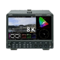
WAVEFORM MONITOR LV5900A
8K/4K/2K/12G/6G/3G/HD
- Home
- Product Info
- Video and Broadcast Related
- LV5900A WAVEFORM MONITOR
- General
- Download
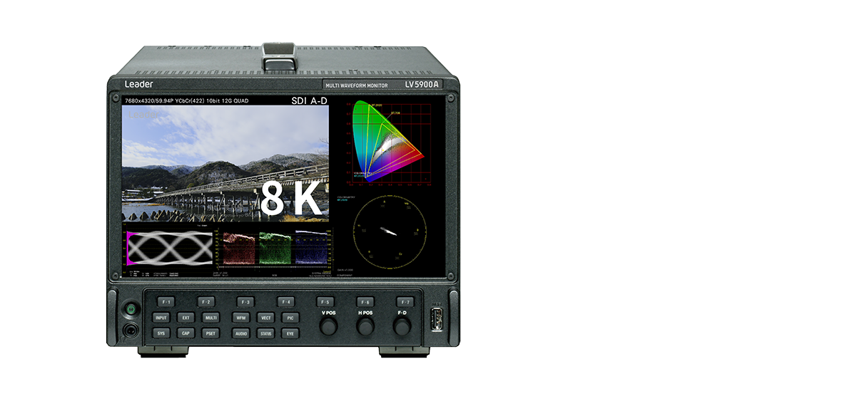
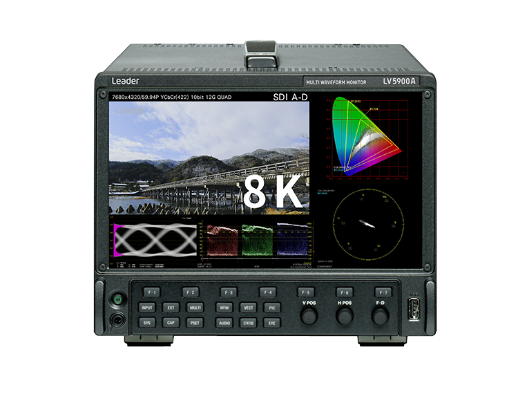
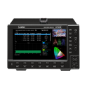
The LV5900A waveform monitor supports SMPTE ST 2082-12, which is used to receive 7680(8192)x4320 / 59.94P YCBCR10bit 8K video via 12G-SDI QUAD LINK. As it supports not only 8K but also a 4k input and four simultaneous HD inputs, you can use it as a high-end 8K system and switch between other systems as needed.
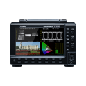
The waveform, vector, picture, and eye pattern display allows for the measurement and quality control of various video signals. The status display allows you to view various error statuses and check on system stability by viewing event logs and long-term charts.
Features
- Superb Operability
The apparatus is designed to give top priority to operability; and further a 9-inch full HD LCD panel featuring excellent view angle and color reproducibility is employed. This model can also be used as a high-grade HD picture monitor. In addition, a touch-panel external monitor connected through USB interface enables intuitive operations and settings through touch operation. - 2K/4K/8K Video Formats
Video formats support includes SDI signals in various formats ranging from, 8K video format with quad link of 12G-SDI, 4K video format with the single link of 12G-SDI, dual link of 6G-SDI, quad link of 3G-SDI and quad link of HD-SDI, in addition to the single link of HD-SDI and 3G-SDI. - Transmission Quality Analysis Function
The LV5900A has feature of enhanced ancillary data analysis functions which includes sync measurement, SDI signal frequency deviation measurement, and equivalent cable length measurement. - Video Analysis Function
For various video signals; quality of experience (QoE) measurement of video signals, such as detection of freeze errors, black errors, gamut errors, in addition to varieties of displays, including the video signal waveform display, vector display, picture display, 5- BAR display and CIE Chromaticity Diagram, are standard features. Errors detected can be recorded as event logs. - Audio Analysis Function
For audio signals, the level meter display, Lissajous waveform display, surround display (not supported for 8K), and loudness display are possible for SDI signals with embedded audio and MADI audio signals externally entered. The signals can also be muted, and clip error detection is possible. Errors detected can be recorded as event logs. - Eye-Pattern Display
The eye-pattern display and jitter display are possible for SDI signals covering from HD-SDI to 12G-SDI. For the measured values, automatic measurement is possible in addition to measurement with a cursor. Furthermore, the histogram can be superimposed on the eye-pattern display for display. - Subtitle/Closed Caption Decode Display Function (Not supported for 8K)
The decode display is possible of Japanese subtitles superimposed onto SDI signals, CEA-608 or CEA-708 closed captions, teletexts, and OP47 subtitles. - Input of External Synchronizing Signal with the Waveform Display Function
Phase differences and synchronization status of all SDI video signals can be checked graphically against external reference synchronizing signal (black burst, tri-level sync signal). - Customizable Layout
Various video signal waveforms, vector display, and pictures of input video signals can be laid out in any of the required positions in the preferred sizes. Multiple input signals up to four inputs can be displayed simultaneously, and one single input signal can be displayed in multiple windows. - SDI Signal Generating Function
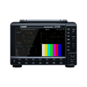
SDI signals covering HD-SDI to 12G-SDI are supported, and 4K video format of Quad Link 3G-SDI and 8K video format of Quad Link 12G-SDI are also supported. Patterns can be output in the form of HD multi-format color bar, 4K multi-format color bar, HDR color bar, etc. - Monitor output connectors
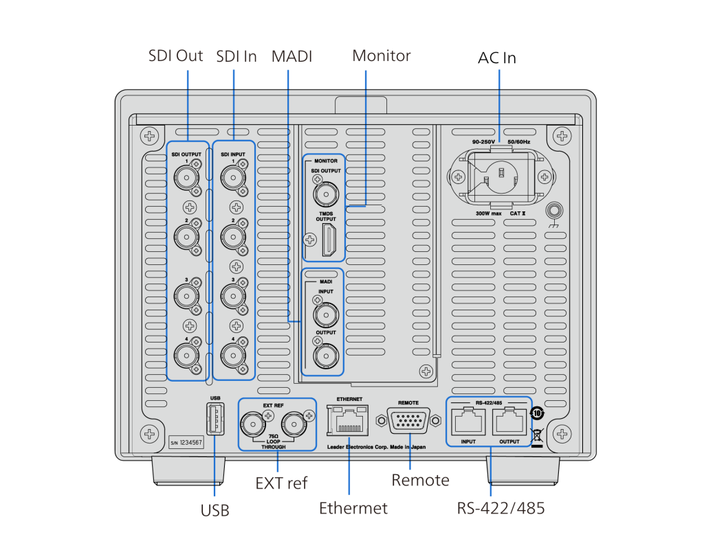
The SDI OUTPUT connector and TMDS OUTPUT connector transmit the instrument’s screen to a full high definition (1920×1080) display for monitoring purposes. - Capture Feature
A screen capture feature, which captures the entire display as still-image data, is available. Not only captured data can be displayed on the instrument, but it can also be compared with an input signal or saved to a USB memory device as bitmap data for viewing on a PC.
A frame capture feature (4K 2-screen display is not supported; only FRM format is supported for 8K) is also available. Frames, including the blanking interval, can be captured. You can set the frame capture function mode to manual or auto, which captures frames when errors occur.
The frame capture data can be viewed and searched through on a PC using a frame capture viewer. - Time Code Display
The timecodes embedded in SDI signals can be displayed. The timecode can also be used as the timestamp in the event log. - External Remote Connector
A contact terminal can be used to load presets, switch the input signal, and transmit alarms. - Ethernet Port
The following features become available when you connect the instrument to a PC: remote control through TELNET, file transfer through FTP, remote control and alarm generation through SNMP, remote control from a Web browser through HTTP, and internal clock synchronization through SNTP. Using the LV7290 REMOTE CONTROLLER (sold separately) allows up to eight LV5900As to be remote controlled. - HDR
Level monitoring of HDR signals supporting S-Log3, C-Log and Log-C in addition to HLG and PQ that are specified in ITU-R BT.2100, and the level management at assumed luminance (Nits)on the display wherein OOTF is taken into consideration are possible. - Focus Assist Function
Development of a new focus detection algorithm in which the non-linear super resolution technology is applied to sensitively enable focusing of low-contrast images that had been hardly detected. - RS-422/485 Connector
For serial communication, you can select the Leader’s standard protocol or TSL protocol. When using the Leader’s standard protocol, you can remotely recall presets, switch the display channel, and display the camera ID, iris, and tally by using serial communication.
When using the TSL protocol, you can control the camera ID (LABEL-1) and tally(TALLY-1,TALLY-2) displays.
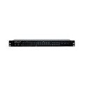
Rear Panel
Login to My Leader is required to download some technical information.
If you have my Leader account, please login from below, if you do not have an account, please create an account and login to my Leader.
